
 EN
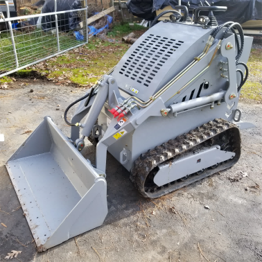
Track Skid Steers in Heavy Mud: Flotation Physics, Tread Mechanics, and Field Efficiency
Key Takeaway: Track skid steers (Compact Track Loaders or CTLs) maintain productivity in saturated mud by operating at an ultra-low ground pressure of 3 to 5 psi—50% lower than wheeled equivalents. To maximize machine availability and eliminate the risk of costly field de-tracking, contractors must match track tread patterns (Zig-Zag vs. Multi-Bar) to local soil plasticity and implement strict daily undercarriage clean-out protocols.
⚖️ The Physics of Flotation: Ground Pressure Dynamics on Saturated Soils
The operational boundary between wheeled skid steers and continuous rubber-tracked loaders is defined by the physics of contact area. When a machine enters saturated clay or silt, the substrate’s bearing capacity drops significantly.
Standard heavy equipment mechanics illustrate the difference in footprint load distribution:
A wheeled skid steer concentrates its entire operating mass onto four small tire contact patches, generating a high ground pressure of 8 to 15 psi. This localized stress exceeds the shear strength of wet soil, forcing the tires to dig downward, create deep ruts, and ultimately high-center the machine's steel belly pan on the mud.
A compact track loader (CTL) distributes its operating mass across the entire length of two continuous rubber tracks, reducing ground pressure to just 3 to 5 psi. This low pressure allows the machine to achieve true flotation, riding along the top surface of the wet clay layer rather than sinking into it. This minimizes soil compaction, reduces subgrade disturbance, and eliminates the remediation costs associated with repairing deep tire ruts in finished landscapes.
? Track Tread Patterns: Maximizing Mechanical Grip in Wet Clay
Traction in mud relies on mechanical shear strength. The tread pattern of the rubber track dictates how effectively the machine can self-clean and maintain directional control.
Zig-Zag Tread Pattern
This pattern features continuous, interlocking angled blocks that provide multidirectional traction. The sharp edges of the zig-zag design slice through liquid slurry, allowing the rubber to bite into firmer subgrade below. This configuration is highly recommended for operations on wet, clay-heavy slopes and embankments, as it prevents lateral sliding during side-slope grading.
Multi-Bar Tread Pattern
Designed primarily for flotation and high-speed transit, the multi-bar pattern utilizes parallel straight bars. It provides a smoother ride on hard surfaces and works exceptionally well in loose sand or light loam. However, in sticky, high-plasticity clay, the narrow gaps between the bars can easily pack with soil, turning the track into a smooth, traction-less belt.
Block Tread Pattern (All-Terrain)
An all-terrain compromise featuring isolated rubber blocks with deep self-cleaning channels. This pattern allows mud to be slung outward by centrifugal force during high-speed rotation. While it offers versatile traction across both muddy soils and hard asphalt, it exhibits accelerated wear when operated continuously on abrasive rocky substrates.
⚙️ Undercarriage Safety: Preventing Mud-Induced De-Tracking
Operating in deep mud subjects the undercarriage system to severe hydraulic and mechanical stresses. Mud accumulation within the track frame is a leading cause of unscheduled downtime.
The De-Tracking Mechanism
As a CTL turns in deep mud, wet clay packs into the drive sprockets, front idlers, and bottom rollers. Once this mud dries or packs tightly, it acts as a solid spacer, artificially increasing track tension.
This over-tensioning overloads the hydrostatic drive motors and increases radial bearing stress. Conversely, if the operator makes a sharp, high-speed pivot turn in deep mud with loose tracks, the packed mud can push the track guide lugs off the center rollers, causing a catastrophic de-tracking event that takes hours of field labor to repair.
Preventive Undercarriage Configurations
To mitigate these risks, modern heavy-duty CTL undercarriages utilize open-frame designs with sloped surfaces that allow mud to fall away naturally. Ground-facing rollers are equipped with dual-cone seals to prevent high-pressure mud slurry from penetrating the bearing cavities and washing out the internal synthetic grease.
?? Field Case Study: Overcoming High-Plasticity Clay in North Florida
During a commercial site preparation project in Pensacola, Florida, consecutive days of heavy rain saturated a site characterized by high-plasticity red clay. The contractor was attempting to complete footing backfills and final perimeter grading.
The contractor initially deployed a fleet of heavy-duty wheeled skid steers. Within two hours, all three wheeled units became high-centered in 6 inches of slick clay muck, requiring a larger excavator to pull them out. The spinning tires also created deep, 12-inch ruts that breached the site’s stormwater erosion control barriers, threatening local regulatory fines.
The Rectification:
The project manager halted wheeled operations and brought in two 4.5-tonne compact track loaders equipped with aggressive zig-zag rubber tracks and sloped open-frame undercarriages.
Operating at a ground pressure of only 4.2 psi, the tracked loaders floated over the rain-softened clay without creating deep ruts or compromising the subgrade.
The operators used the machines to grade the perimeter and secure the silt fences, completing the backfill in half the projected timeline. By avoiding weather-related stoppages and eliminating rut remediation, the contractor saved an estimated $4,500 in daily labor and equipment rental costs.
? Undercarriage Maintenance & Selection Audit Checklist
Before deploying a compact track loader into muddy C&I construction zones, fleet mechanics and site superintendents must verify compliance with the following:
| Verification Parameter | Industrial Benchmark / Standard | Verification Method |
|---|---|---|
| Track Tension (Sag) | 10 to 15 mm of sag at the center roller | Physical measurement under auxiliary lift; adjust grease cylinder. |
| Roller Seal Integrity | Zero oil leakage from dual-cone roller seals | Visual inspection of inner roller faces for wet grease residue. |
| Tread Depth | Minimum 50% lug height remaining for mud service | Calibrated tread depth gauge measurement. |
| Drive Sprocket Wear | Symmetrical tooth profiles without sharp hooking | Visual inspection of sprocket teeth for thinning or wear patterns. |
Table of Contents
-
Track Skid Steers in Heavy Mud: Flotation Physics, Tread Mechanics, and Field Efficiency
- ⚖️ The Physics of Flotation: Ground Pressure Dynamics on Saturated Soils
- ? Track Tread Patterns: Maximizing Mechanical Grip in Wet Clay
- ⚙️ Undercarriage Safety: Preventing Mud-Induced De-Tracking
- ?? Field Case Study: Overcoming High-Plasticity Clay in North Florida
- ? Undercarriage Maintenance & Selection Audit Checklist